
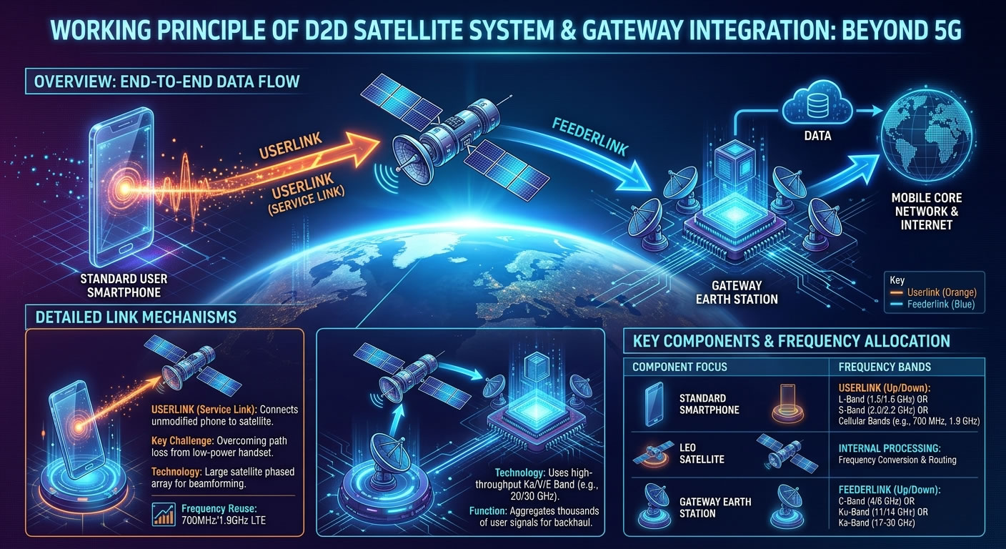

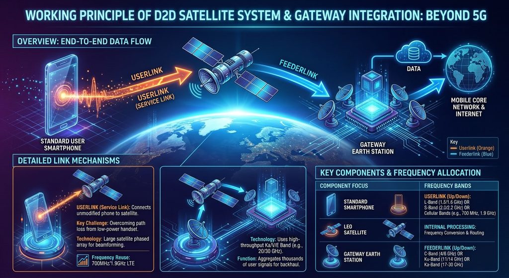
The working principle and frequency configuration of Gateway Earth Stations and Direct-to-Device (D2D) satellite services:
1. Core Working Principle of Satellite D2D Services
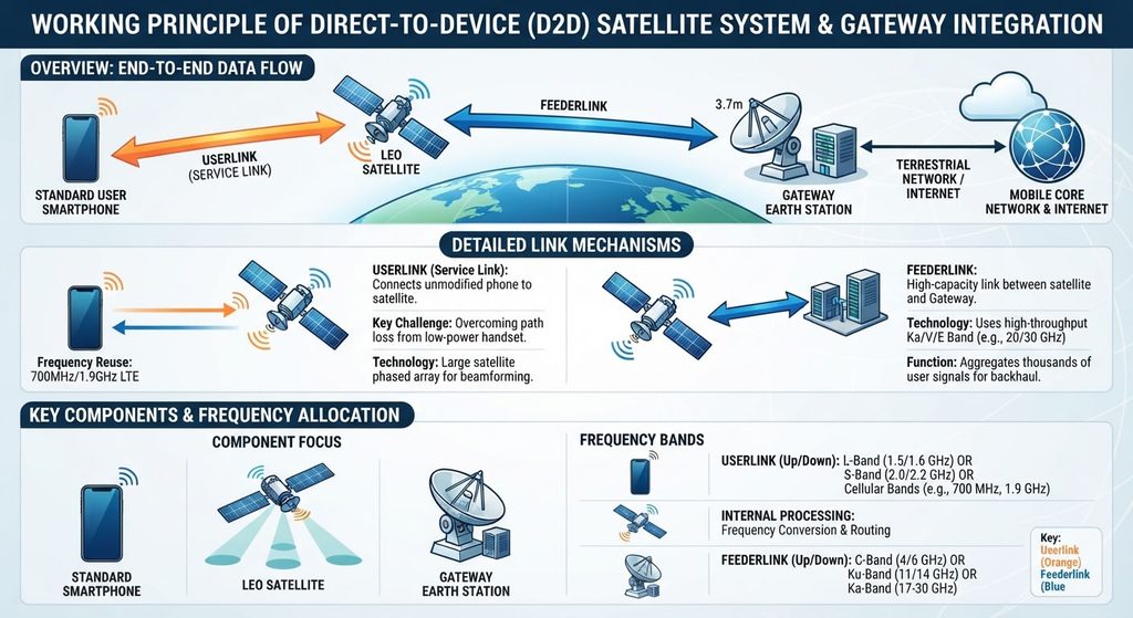
The essence of satellite D2D service lies in “Direct connection between standard ground terminals and satellites” + “Transparent forwarding/routing by satellites to ground gateways.” The data transmission architecture is divided into two primary links:
1.1 Userlink (Service Link): Handset ↔ Satellite
- Uplink (Handset Transmit): Standard smartphones (or dedicated handheld terminals) on the ground transmit voice, SMS, or data signals into space via radio waves. Since the transmit power of a mobile phone is extremely low (typically around 200mW), Low Earth Orbit (LEO) satellites must deploy massive phased array antennas (often dozens of meters wide) to capture these weak signals.
- Downlink (Satellite Transmit): Satellites project signals precisely onto specific geographical areas on Earth using high-gain spot beams, which are then received directly by unmodified smartphones.
1.2 Feederlink: Satellite ↔ Gateway Earth Station
- Downlink (Satellite Forwarding): After receiving signals from thousands of handsets, the satellite performs frequency conversion and aggregation. It then concentrates these data streams into highly directional, high-bandwidth microwave beams directed at the ground gateway station.
- Uplink (Gateway Backhaul): Upon receiving the data forwarded by the satellite, the gateway routes it directly into terrestrial Mobile Core Networks (MNO) or the internet via high-speed fiber-optic backhauls. Reverse traffic follows the exact opposite path: from the gateway up to the satellite, and then distributed down to individual mobile phones.
2. Frequency Configuration Options for Satellite D2D Services
To avoid mutual interference and ensure transmission efficiency, the Userlink and Feederlink must operate on completely different frequency spectrums. The industry primarily follows two distinct approaches globally:
Scenario A: Cellular Spectrum Reuse Mode (Mainstream Trend, e.g., Starlink, AST SpaceMobile)
This approach features a “no-hardware-change” model for consumers, where satellites transmit on the existing terrestrial spectrum owned by Mobile Network Operators (MNOs).
- Userlink Frequency:Sub-1GHz or Sub-2.5GHz Terrestrial Cellular Bands
- Common Bands: 700 MHz (Band 28/85), 800 MHz (Band 20), 1900 MHz (Band 25).
- Rationale: Low-frequency bands feature superior penetration capabilities and minimal free-space path loss, making them ideal for the weak signals of standard, unmodified smartphones reaching space.
- Feederlink Frequency:Ka / V / E Bands (Extremely High Frequency, Ultra-Wide Bandwidth)
- Common Bands:
- Ka-Band: Uplink 27.5–30.0 GHz / Downlink 17.7–20.2 GHz.
- V/E-Bands: 40–50 GHz / 70–80 GHz (Future trend for massive throughput).
- Rationale: Because the data of thousands of smartphones is aggregated into a single pipe, the gateway must use millimeter-wave bands that offer massive bandwidth capacity.
- Common Bands:
Scenario B: Traditional Mobile Satellite Services (MSS) Mode (e.g., Apple + Globalstar, Iridium)
This approach requires dedicated satellite bands to be natively integrated at the hardware/chipset level within the smartphone (such as the emergency satellite messaging feature in iPhone 14 and newer models).
- Userlink Frequency:L-Band and S-Band
- Common Bands:
- L-Band (1.6 / 1.5 GHz): Traditionally used by Iridium and Globalstar for uplinks.
- S-Band (2.0 / 2.2 GHz): Used by Tiantong-1 and supported by newer satellite-enabled commercial smartphones.
- Rationale: These are dedicated spectrum allocations managed by the International Telecommunication Union (ITU) specifically for mobile satellite services, minimizing terrestrial interference but requiring specialized device antennas.
- Common Bands:
- Feederlink Frequency:C-Band or Ku-Band
- Common Bands:
- C-Band: Uplink 5.0–5.2 GHz / Downlink 6.7–7.0 GHz (e.g., legacy Globalstar architecture).
- Ku-Band: Uplink 14 GHz / Downlink 11 GHz.
- Rationale: Traditional MSS systems have lower total data throughput requirements compared to broadband constellation networks, meaning mature C or Ku-band hardware is sufficient to handle the gateway backhaul.
- Common Bands:
3. Summary Comparison Table
| Mode Category | Userlink Spectrum (Handset ↔ Satellite) | Feederlink Spectrum (Satellite ↔ Gateway) | Representative Operators | Device Requirement |
| Cellular Spectrum Reuse (D2D/D2C) | 700MHz / 800MHz / 1.9GHz Ground Cellular Bands | Ka / V / E Bands (Ultra-high capacity) | SpaceX (Starlink) AST SpaceMobile | Standard Smartphones without any hardware modifications. |
| Traditional Dedicated (MSS) | L-Band / S-Band (Satellite-dedicated mobile spectrum) | C-Band / Ku-Band (Mature and stable) | Apple (Globalstar) Iridium | Custom Chipset/Antenna (e.g., Satellite SMS, Satellite Phones). |